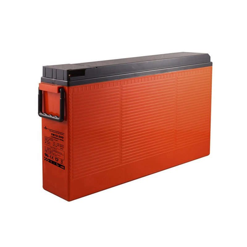
Solar Gel Battery - 12v 200ah Front Terminal Telecom Lead acid battery Battery – ShaoBo
Solar Gel Battery - 12v 200ah Front Terminal Telecom Lead acid battery Battery – ShaoBo Detail:
Applications
➢ Telecom Control Equipment
➢ UPS systems, Inverter
➢ Power Equipment
➢ Solar & Wind
➢ Emergency Power Systems
General Features
✓ Advanced AGM technology, and Maintenance-free operation;
✓ Front access terminal with standard width for 19” and 23” ETSI racks;
✓ Fire resistance ABS container;
✓ Long float service life 10years;
✓ Low self discharge.

COMPLIED STANDARDS
IEC 60896-21/22
JIS C8704 YD/T799
BS6290 part4
GB/T 19638 CE

Dimensions & Weight
| Length(mm) | 560±1 |
| Width(mm) | 125±1 |
| Height(mm) | 316±1 |
| Total Height(mm) | 316±1 |
| Weight(kg) | 57.0±3% |
Technical Specifications
| Nominal Voltage | 12V(6 cells per unit) | |||
| Design Floating Life @25℃ | 10 Years | |||
| Nominal Capacity @25℃(10 hour rate@20.0A,10.8V) | 200Ah | |||
| Capacity @25℃ | 20hour rate (10.6A,10.8V)5hourrate(35.2A,10.5V) 1hourrate(127.6A,9.6V) | 212Ah176Ah127.6Ah | ||
| Internal Resistance | Full Charged Battery@25℃ | ≤3.2mΩ | ||
| Ambient Temperature | Discharge ChargeStorage | -15℃~45℃-15℃~45℃-15℃~45℃ | ||
| Max.Discharge Current@25℃ | 2000A(5s) | |||
| Capacity affected by Temperature(10 hour ) | 40℃25℃0℃-15℃ | 105%100%85%65% | ||
| Self-Discharge@25℃ per Month | 3% | |||
| Charge (Constant Voltage) @25℃ | Standby Use | Initial Charging Current Less than 50A Voltage 13.6-13.8V | ||
| Cycle Use | Initial Charging Current Less than 50AVoltage 14.4-14.9V | |||
Battery Discharge Table
Discharge Constant Current per Cell (Amperes at 25°C)
| F.V/Time | 10min | 15min | 30min | 45min | 1h | 2h | 3h | 5h | 8h | 10h | 20h |
| 1.60V | 465.0 | 361.0 | 216.6 | 161.0 | 127.6 | 75.0 | 55.2 | 37.2 | 25.4 | 21.0 | 11.1 |
| 1.65V | 430.2 | 341.0 | 209.4 | 154.8 | 123.8 | 72.6 | 53.4 | 36.6 | 25.2 | 20.6 | 11.0 |
| 1.70V | 399.0 | 320.2 | 203.6 | 149.2 | 119.0 | 70.6 | 52.0 | 35.8 | 24.8 | 20.4 | 10.9 |
| 1.75V | 372.6 | 300.0 | 193.0 | 142.6 | 114.2 | 68.8 | 50.8 | 35.2 | 24.4 | 20.2 | 10.8 |
| 1.80V | 335.2 | 281.4 | 186.2 | 137.4 | 110.2 | 66.2 | 49.2 | 34.4 | 24.0 | 20.0 | 10.6 |
Discharge Constant Power per Cell (Watts at 25°C)
| F.V/Time | 10min | 15min | 30min | 45min | 1h | 2h | 3h | 5h | 8h | 10h | 20h |
| 1.60V | 836.4 | 690.2 | 422.2 | 305.8 | 244.8 | 142.2 | 105.4 | 71.8 | 49.6 | 41.0 | 21.4 |
| 1.65V | 782.8 | 660.4 | 403.8 | 295.4 | 238.2 | 138.4 | 102.6 | 70.6 | 49.2 | 40.6 | 21.2 |
| 1.70V | 733.0 | 615.4 | 387.2 | 286.0 | 230.0 | 135.2 | 100.2 | 69.6 | 48.6 | 40.2 | 21.0 |
| 1.75V | 689.8 | 577.4 | 368.6 | 274.6 | 221.6 | 132.0 | 98.2 | 68.6 | 48.0 | 39.8 | 20.8 |
| 1.80V | 624.4 | 542.0 | 353.6 | 265.4 | 214.4 | 127.6 | 95.4 | 67.2 | 47.4 | 39.6 | 20.6 |
Note: The above data are average values, and can be obtained within 3 charge/discharge cycles. These are not minimum values. Cell and battery designs/specifications are subject to modification without notice. Contact CSBattery for the latest information.


Battery Construction
| Component | Positive plate | Negative plate | Container &Cover | Safety valve | Terminal | Separator | Electrolyte | Pillar sea |
| Features | Thick high Sn low Ca grid with special paste | Balanced Pb-Ca grid for improved recombinati on efficiency | Fire resistance ABS (UL94-V0 optional) | Flame Si-Rubber and aging resistance | Female Copper Insert M6(torque :3~4N.m | Advanced AGM separator for high pressure cell design |
Dilute high purity sulfuric acid | Two layers epoxy resin seal |
Product detail pictures:

Related Product Guide:
Our mission will be to become an innovative supplier of high-tech digital and communication devices by furnishing benefit added structure, world-class manufacturing, and service capabilities for Solar Gel Battery - 12v 200ah Front Terminal Telecom Lead acid battery Battery – ShaoBo , The product will supply to all over the world, such as: Germany, Hongkong, Cambodia, We have a dedicated and aggressive sales team, and many branches, catering to our main customers. We are looking for long-term business partnerships, and ensure our suppliers that they will definitely benefit in both short and long run.
Good quality and fast delivery, it's very nice. Some products have a little bit problem, but the supplier replaced timely, overall, we are satisfied.

